
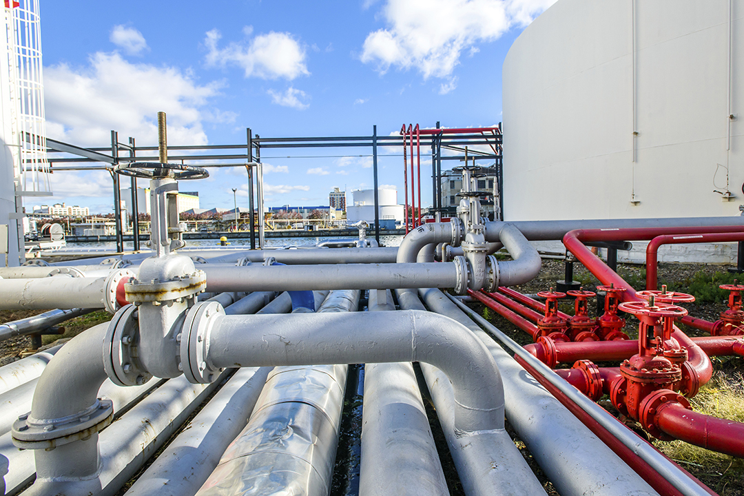
Leak failures in industrial piping systems rarely announce themselves with drama. They develop quietly at connection points — flanges left with inconsistent bolt torque, gaskets seated on faces that were never properly cleaned, or pipe materials that were never spec’d for the actual operating pressure in the first place. By the time process fluid is escaping, the damage is already compounding: unplanned downtime, environmental liability, regulatory exposure, and emergency repair costs that dwarf whatever was saved during procurement.
Building a leak-free piping system in an industrial plant requires attention at every stage, from pipe specification through flange selection, gasket material matching, bolt grade, and final assembly torque sequence. There is no single component that guarantees a tight system. It is the combination of correct materials, correct assembly, and consistent flange bolting practices that determines whether a system holds through years of operating cycles or fails at the first pressure surge.
Why Flange Connections Are the Highest-Risk Points in Any Piping System
A flanged joint is a mechanical seal under sustained load. The pipe itself, whether carbon steel, stainless, HDPE, or PVC, carries the medium with relatively low failure risk when correctly spec’d for the service. But every flanged connection introduces a potential leak path. The gasket must compress evenly across the full seating area, the bolts must maintain adequate clamping load through thermal cycles and system vibration, and the flange faces must be clean and within dimensional tolerance when the joint is assembled.
According to ASME standards — particularly ASME B16.5 for pipe flanges and flanged fittings and ASME B16.20 for ring joint gaskets — flanged connections must meet specific dimensional tolerances, material grades, and pressure-temperature ratings for the joint to perform safely under operating conditions. Those standards exist because the industry learned, through decades of documented failures, that flanged connections require engineering precision, not just mechanical assembly.
In refineries, chemical plants, municipal water facilities, and oilfield gathering systems across Texas, flange leaks remain among the most common root causes of unplanned shutdowns. Reducing that risk starts with understanding what actually makes a flanged connection fail at each stage of its life.
Pipe Material Selection Sets the Stage Before the Flange Is Ever Touched
Before a flange gets bolted, the right pipe material has to be in the ground. The material determines the pressure class, thermal expansion behavior, chemical compatibility, and what kind of flange and gasket combination can be used at the connection point. Getting this wrong upstream creates a sealing problem that no amount of correct flanging will fix.
Carbon steel pipe is the workhorse of industrial and oilfield piping. It handles high pressures, elevated temperatures, and heavy mechanical loads. It flanges cleanly and accepts the widest range of gasket materials. It does corrode in wet or chemically aggressive environments, which is why material selection must account for the service fluid, operating temperature, and corrosion allowance designed into the system from the start.
Stainless steel pipe, particularly 304 and 316 grades, is the choice where corrosion resistance matters more than raw material cost. In food processing, pharmaceutical, chemical, and marine applications, stainless flanged systems are the operating standard. The flanges, bolts, and gaskets used in stainless systems need to match the corrosion performance of the pipe itself. Using standard carbon steel hardware in a stainless system creates a galvanic cell at every connection point and undermines the corrosion protection the pipe material was selected to provide.
HDPE pipe changes the connection equation significantly. HDPE is typically joined through butt or socket fusion, but where HDPE systems terminate at pumps, valves, or steel piping, flanged connections become necessary. Those transitions — HDPE stub-end flanges connecting to carbon steel or stainless flanges — require careful gasket selection and controlled bolt torque because HDPE flanges are not rigid in the same way metal flanges are. Over-torquing will crack the stub end. Under-torquing leaves the gasket unseated.
Coastal Resource Group stocks carbon steel pipe and stainless steel pipe alongside a full HDPE inventory across DR ratings and PE grades. For projects that involve multiple pipe materials connecting through flanged joints, sourcing all of it from a single Texas supplier removes the coordination friction that slows procurement on active construction schedules.
Flange Types and How Geometry Affects Seal Performance
Not all flanges are interchangeable, and the selection is not just dimensional. The flange type determines the sealing geometry, the compatible gasket style, the bolt pattern loading, and the pressure-temperature rating of the joint. Specifying the wrong type for the service or mixing face types at a connection is a common field error that produces leaks once the system reaches operating pressure.
The most widely used industrial flanges each serve a defined purpose:
- Weld Neck Flanges — welded to the pipe at the neck with a full-penetration butt weld. The bore matches the pipe ID, reducing turbulence and stress concentration. Standard for high-pressure and high-temperature critical service applications.
- Slip-On Flanges — slide over the pipe end and are fillet-welded in place. Lower cost than weld neck, suitable for lower-pressure general service. Not recommended for cyclic loading or elevated temperature applications.
- Socket Weld Flanges — designed for small-bore pipe, typically 2 inches and under, in high-pressure service. The pipe inserts into the socket and is fillet-welded. Better fatigue resistance than slip-on for small diameters.
- Lap Joint Flanges — used with stub-end fittings. Common where frequent disassembly is required and at HDPE-to-steel transitions where bolt hole alignment flexibility is needed.
- Blind Flanges — solid-disc flanges used to terminate a line. Standard at inspection ports, future tie-in locations, and pressure test endpoints.
- Raised Face vs. Flat Face — raised face concentrates bolt load on a smaller seating area and is the default for steel systems. Flat face is required when connecting to cast iron flanges or HDPE stub ends to prevent cracking from uneven load distribution across the face.
Coastal Resource Group’s industrial flange inventory covers the full range of types and pressure classes. For projects that need flanges alongside pipe, fittings, and hardware sourced from one vendor, the supply chain simplification is measurable in project hours.
Pipe Flange Gasket Assembly: Where Most Leaks Are Actually Created
The gasket is where the seal lives. It fills the microscopic surface irregularities between two flange faces and creates the barrier that contains process fluid under pressure. Select the wrong gasket material for the service fluid, install it on a contaminated flange face, or torque the bolts in the wrong sequence, and no amount of correct pipe or flange specification will save the connection from leaking.
Pipe flange gasket assembly failures follow a predictable pattern. In most cases, the root cause is one of four conditions: gasket material incompatible with the service fluid or temperature, flange faces not cleaned before assembly, bolt torque applied unevenly or in the wrong cross-pattern, or gasket reuse after the original connection was opened. Any single one of these conditions is enough to produce a leak. A combination of two or more is close to a certainty.
The major gasket material categories each serve a defined service range:
- PTFE (expanded or full-face) — broad chemical resistance, suitable for chemical service, water treatment, and corrosive fluid applications. Commonly used in HDPE-to-steel transitions and carbon steel chemical service flanges.
- Elastomers (EPDM, Buna-N/NBR, Neoprene) — flexible and forgiving on lower-pressure systems. EPDM is standard in municipal water systems. NBR is used where hydrocarbon exposure is possible. Neoprene handles moderate chemical and ozone exposure.
- Spiral Wound Gaskets — metal wound with soft filler (PTFE or graphite), used in high-pressure and high-temperature steel flanged systems. Standard in refinery and petrochemical service.
- Flexible Graphite — handles extreme temperatures, steam service, and aggressive process chemicals. Common in power generation and refinery high-cycle flanged connections.
- Ring Joint (RTJ) Gaskets — soft metal rings for high-pressure wellhead and subsurface flanges. Require RTJ-grooved flange faces and are not interchangeable with raised face or flat face configurations.
For projects involving HDPE piping connected to steel flanged equipment in chemical plant environments, CRG has published a detailed look at gasket material selection for HDPE-to-steel flange transitions that covers the compatibility decisions procurement teams most frequently face.
Bolt Grade, Torque Sequence, and the Mechanics of Even Compression
The gasket does not seal by itself. It compresses under bolt clamping load, and the quality of that compression is entirely determined by the bolt grade used and the torque sequence followed during assembly. A large percentage of field-assembled flanged joint leaks trace back not to wrong materials, but to bolts run down in the wrong order or to inconsistent torque values that left part of the gasket face unseated.
Industrial flange bolts are specified by grade, and each grade carries a defined tensile strength, yield strength, and appropriate torque range. Using the wrong bolt grade produces either insufficient clamping load to seat the gasket under pressure or excess load that damages the flange face or crushes the gasket beyond its design compression range.
| Bolt Grade | Material | Typical Service | Notes |
|---|---|---|---|
| ASTM A193 B7 | Chromium-molybdenum alloy steel | High-pressure, high-temperature, petrochemical, oil and gas | Most common industrial flange bolt; excellent strength retention at elevated temperatures |
| ASTM A193 B8 | Austenitic stainless steel (304) | Corrosive service, stainless piping, food processing, chemical | Matched to stainless flanges to prevent galvanic corrosion at the connection |
| ASTM A307 | Carbon steel | Low-pressure, ambient-temperature general service | Not suitable for elevated temperature or critical service applications |
| ASTM A320 L7 | Alloy steel, low-temperature rated | Cryogenic and low-temperature service, LNG, cold processing | Maintains toughness and impact resistance at sub-zero operating temperatures |
The torque sequence matters as much as the torque value. Bolts should be advanced in a cross-pattern — not clockwise around the flange — to distribute clamping load evenly across the full gasket face. Standard practice is to hand-tighten all bolts first, then torque in three passes at 30%, 70%, and 100% of target torque, always following the cross-pattern. After the system reaches operating temperature for the first time, re-torquing while the system is hot corrects gasket relaxation and thermal set that occur in the initial heat cycle. Skipping that re-torque step is a common cause of leaks that develop within the first weeks of service on new construction.
CRG stocks ASTM A193 B7 bolts along with B8 and full ASTM A193 grade hardware through their industrial flanges and flange bolts supply line — available alongside the flanges and pipe so procurement teams can close the entire material list from one source rather than chasing separate vendors for hardware that lands on the same job site at the same time.
What Causes Flanged Systems to Leak After Start-Up
A connection can pass hydrostatic testing and still develop a leak under sustained operating conditions. The failure modes are well-documented. Thermal cycling causes bolt load to relax as metal expands and contracts with temperature changes. Gasket creep, the slow compression of gasket material under sustained load, reduces seating stress over time, particularly with softer elastomeric and PTFE materials at higher temperatures. Vibration from pumps, compressors, and turbulent flow introduces fatigue loading that initial torque cannot permanently resist.
In HDPE piping systems connected to steel flanged equipment, differential thermal expansion between the two materials adds stress at the transition point with every temperature cycle. These connections require flat-face flange configurations, appropriate gasket durometer for the operating range, and controlled bolt torque to manage the differential movement without cracking the HDPE stub end or progressively losing gasket seating load.
Corrosion under insulation is a specific and common failure mechanism in insulated carbon steel flanged systems. Moisture infiltrates insulation at flanged joints because the joint geometry creates natural intrusion points. That moisture accelerates corrosion on the flange face, bolts, and gasket seating area in a way that is invisible until the system is opened. Scheduled inspection at flanged connections in insulated systems is an operational requirement, not optional maintenance.
Assembly and Inspection Practices That Keep Flanged Systems Tight Over Time
The plants with the fewest flange leaks are the ones with systematic inspection and maintenance programs built specifically around connection points. That means scheduled visual inspections for weeping joints, periodic bolt load verification on critical-service flanges, and documented torque records that follow every connection through its service life. These are not complicated disciplines. They are consistent ones.
A few practices consistently separate plants with reliable flanged systems from those that treat leaks as an expected condition of operation:
- Inspect flange faces before every assembly. Clean the faces, check for pitting, scoring, or tool marks, and verify the seating area is within dimensional tolerance. Even minor surface damage prevents the gasket from seating evenly under pressure.
- Never reuse a compressed gasket. Once a gasket has been compressed and released, its seating geometry has changed permanently. Reuse is a direct path to a leak, and the cost of a replacement gasket is trivial against the cost of another opening.
- Re-torque after the first heat cycle. Especially critical in high-temperature systems where gasket relaxation and thermal set are normal mechanical outcomes. Re-torquing corrects them before they open a leak path.
- Match all hardware to the same service conditions. Flanges, bolts, and gaskets for a single connection should all be selected together for the same pressure class, temperature range, and fluid compatibility. Mixing grades or material families across one joint introduces the weakest link into the seal.
- Document every critical-service flanged connection. Bolt grade, gasket material, achieved torque values, and inspection dates should be on record. When a leak occurs, that documentation is the fastest path to identifying the failure mode and preventing the same failure from recurring elsewhere in the system.
Building a piping system that holds is not an accident. It is the result of correct specification at every stage: pipe material, flange type, gasket selection, bolt grade, flange bolting sequence, and post-startup inspection. When those components come from a supplier who stocks them together and understands how they work as a system, procurement becomes part of the engineering process rather than a separate obstacle working against it.
Coastal Resource Group supplies industrial flanges, bulk flange bolts, carbon steel, stainless steel, and HDPE pipe, and related MRO hardware across Texas. Call 888-841-7954 or request a quote to get the right materials on-site when your schedule demands it.